Why 3D simulation before physical installation
Designing a robot cell on paper or in CAD is necessary — but insufficient. A 2D layout doesn't tell you whether the robot can actually reach position 47 without hitting the fixture. It doesn't show you whether the cycle time works when the gripper needs to rotate 180°. And it can't warn you about the collision that will happen when the conveyor is running and the robot is at its home position at the same time.
3D robot simulation closes this gap. Before anything is fabricated or installed, you have a virtual cell that replicates the kinematic behaviour of every robot, the movement of every conveyor, and the timing of every sequence — and you can run it for days to find every problem.
Design changes in simulation cost nothing. The same change after physical installation — moving a robot base by 200mm, adding a safety fence, rerouting a cable tray — typically costs thousands of euros and weeks of delay.
See it in practice
Automotive welding cell — reach analysis & offline programming
Visual Components · Automotive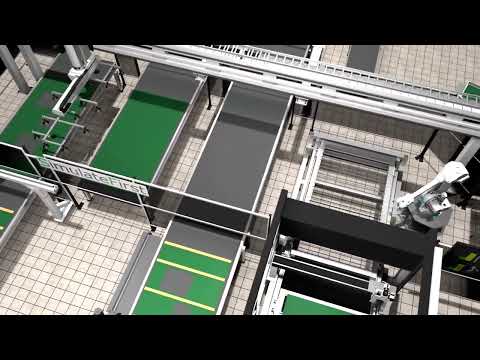
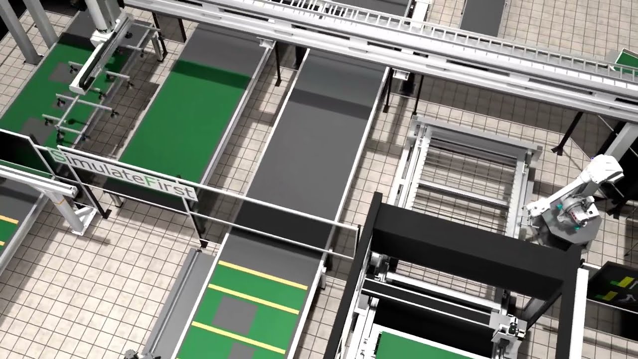
Automated wall assembly line — robot kinematics & laser cutting
Visual Components · Manufacturing
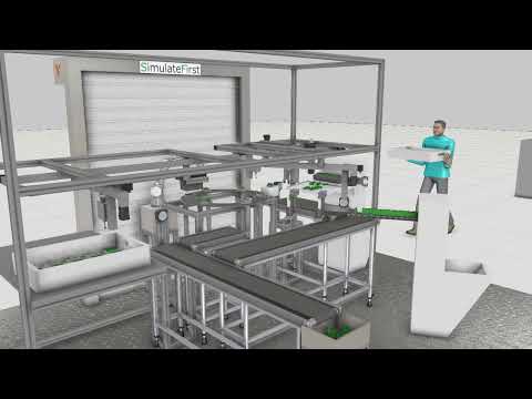
Entire factory layout — material flow & throughput analysis
Visual Components · ManufacturingWhat we simulate and what you can test
Our Visual Components models replicate the physical reality of your cell with full kinematic fidelity. This includes:
- Robot reach and reachability analysis — verify every tool position is within the robot's workspace without singularities
- Collision detection — identify interference between robots, fixtures, guards, conveyors, and workpieces at any point in the cycle
- Cycle time analysis — measure actual cycle time including all moves, waits, and handoffs — not theoretical calculations
- Multi-robot coordination — model concurrent operation and interlocking of multiple robots in shared workcells
- Conveyor and material flow — simulate part movement, buffering, and pacing between stations
- Layout optimisation — compare alternative equipment positions and orientations to find the most efficient arrangement
CAD data & specification import
We start from your CAD layout (STEP, IGES, or native format), robot selection, and process specification. Machine and component CAD files from suppliers are imported or replaced with library equivalents.
3D model build & kinematics
We build the full kinematic model — robots from the Visual Components library, custom fixtures, conveyors, sensors, and guards. Every component that moves is modelled accurately.
Programming & sequence simulation
Robot programs are written in the simulation. Sequences are defined, tested, and timed. All coordination logic, interlocks, and concurrent motions are validated.
Analysis, optimisation & output
Cycle time reports, reach maps, collision analysis, and alternative layout comparisons. Offline robot programs generated and exported. Full model and documentation delivered.
What you get at the end
Deliverables: the Visual Components model file, a cycle time report, collision analysis, offline robot programs for all robots, layout comparison documentation (if alternatives were tested), and a recorded walkthrough video of the simulated cell for stakeholder presentations.
Robot brands & system components supported
Visual Components includes models from all major robot manufacturers — plus conveyors, grippers, safety systems, and thousands of industrial components. We can import custom machine CAD for components not in the library.
From sales demo to engineering simulation
Many projects start with a visual 3D demo — a compelling animation of the proposed automation solution to win the order or align stakeholders. Once the project is approved, the same Visual Components model is developed further into a full engineering simulation: reach verification, cycle time analysis, offline robot programs, and virtual commissioning. One model, two stages of the project.