
Simulation for robots, machines and automation using Visual Components
From robot simulation up to offline programming and virtual commissioning.

Detailed Simulation of Robots and Machines

From Static CAD Models to Dynamic 3D Constructions

Clear Evaluations with 3D Visualization and 3D PDF Reports

Real-World Applications and Success Stories
High-class robot simulation with Visual Components
Streamlined robot simulation and programming with an extensive library of leading brands
Visual Components features an extensive open library. It includes over 1000 predefined robots. These robots come from top brands like Kuka, ABB, Stäubli, Fanuc, Motoman, Kawasaki, and more.
It provides a unified programming interface that simplifies robot programming across different models. Additionally, you can save programs tailored to each robot type’s unique specifications. This ensures seamless compatibility and efficiency.

Simulating machines and systems with joints: from CAD files to fully functional components
The open library also includes a wide range of predefined systems. If a specific component is missing, it can be easily created from its CAD file. These custom components can include movable or rotating or movable arms and sections.
Additionally to CAD geometries, each component requires a control mechanism to define its operational behavior.

Intuitive Robot Programming and Seamless Simulation to-Implementation
Robots and other jointed components can be effortlessly programmed within the layout editor. Programming is intuitive—for instance, simply move the robot head to a desired position and click to record it. You can also incorporate logical commands like ‘IF’ or ‘WHILE’. This helps to build a comprehensive, dynamic program for the robot within the layout. Once the simulation is run, the robot executes the program exactly as defined. Additionally, this program can be exported directly for use with the real robot, streamlining the transition from simulation to implementation.

Seamless Integration with Real-World Systems via Signal-Based Communication
Visual Components utilizes signals to seamlessly send events and data between components within the model. This powerful signaling system enables integration with real-world systems. VC can connect effortlessly to PLC software, robot controllers, and hardware. It uses protocols like OPC UA, PLC Sim, TwinCAT (Beckhoff), and more.

Simulating Physical Interactions and Behavior of Components
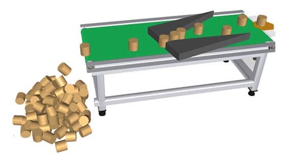
Components can be assigned physical properties. These include free fall, braking, and acceleration. They may also interact with other bodies, like being blocked or aligned. For example, watch as cylinders fall, stack, and align with one another in the image to the side.
Automated Collision Prevention and Component Monitoring in Simulations
To prevent collisions between components, it’s recommended to define a minimum distance between them. During the simulation, this distance is continuously monitored. If the gap falls below the specified threshold, the simulation is automatically halted, and the affected component is highlighted in color for easy identification

Unlocking the Benefits of CAD Simulation: Enhancing Design and Efficiency
Seamless CAD Import Across Multiple Formats
VC imports CAD directly from several formats. These include Step, Catia, SolidWorks, and Unigrafics. It also imports from AutoCAD, Parasolid, and JTOpen. Additionally, VC supports Iges, Igrip, 3D Studio, Sketchup, and Rhino, among many more CAD formats.
Optimizing Motion Control with Simplified CAD and Kinematic Programming
After importing, CAD geometries are simplified and divided into smaller, independent components. These components can then be linked using joints, like rotary axes or linear tracks. Each joint can be assigned specific properties or programmed to replicate precise motion behaviors. For instance, joints in a robotic system can be controlled through kinematic routines. This control enables the robot to move accurately. It also helps position the robot within a defined space.

Streamlining Collaboration with 3D PDF Exports in Visual Components
Visual Components allows you to export a 3D layout as a 3D PDF. This simplifies collaboration within project teams. It also provides a clear reference for customers. You can easily open these 3D PDFs with the widely available Acrobat Reader. This ensures accessibility and usability across various stakeholders.
Quality analysis of the simulation runs
Dynamic Visualization of Performance Metrics in Visual Components
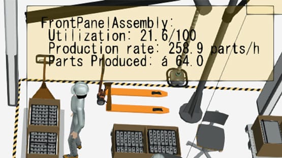
Visual Components enables versatile presentation of results, offering detailed insights into key performance metrics. Components automatically collect and visualize statistics like utilization. They also gather data on production rates and production volumes directly within the model. This provides a clear and interactive way to analyze and share outcomes.
Insightful Monitoring with Real-Time Simulation Dashboards
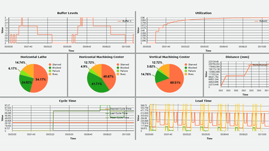
During a simulation run, statistical values can be recorded and displayed in an intuitive dashboard. This allows you to track data like buffer quantities over time or the real-time positions of a robot’s axes. By visualizing how each axis operates and identifying the most heavily utilized ones, you gain valuable insights into system performance. Well organized dashboards simplify the analysis of complex interactions, making it easier to understand and improve the behavior of modeled systems.
See some of our examples
Take a Visual Components training course with SimulateFirst!
Whether you’re simulating robots, machines, or entire production layouts in Visual Components, our courses will guide you through the process of mastering component modeling, layout building as well as robot programming. With hands-on experience, you'll gain the knowledge to optimize designs and analyze production processes. No matter your schedule, we offer flexible trainings tailored to your needs. Start your journey towards 3D simulations today! Contact us for more details.
CONTACT US
Distance is no obstacle – We’ve successfully collaborated online with clients in the USA, Sweden, France, Denmark, Portugal and beyond.
+49 351 30906020dresden@simulatefirst.comPARTNERS:

