Simulation for robots, facilities, special machines and automation
From robot simulation up to offline programming and virtual commissioning.

Simulate robot and machines in detail

Static CAD in 3D-moving construction

Display evaluations clearly and in 3D PDF

Examples, Visual Components in action
Robot simulation on high class niveau
One simulation with many robot brands
Visual Components has over 1000 predefined robots in its open library of such brands as Kuka, ABB, Stäubli, Fanuc, Motoman, Kawasaki and more.
It offers a unified robot programming interface for all those robots. And at the same time it can save this program for many of these robots uniquely to its type.

Machines and systems with joints
Many other systems are also predefined in the open library. If a component is missing then it can be created out of its CAD file. This component may have rotating or movable arms and sections.
Apart from CAD geometries the component needs a control mechanism that defines how it will operate.

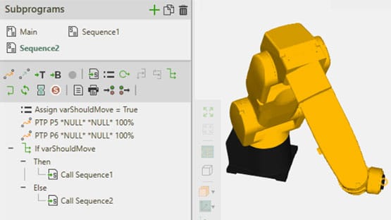
Easy programming
Robots as well as all other components with joints can be easily programmed for the given layout in an editor. For example it is enough to bring the robot head to a new position, then click the mouse which records the position of the robot. Decisions such as „IF" or “While” can be also used here. This creates a complete program for the robot in the layout. After starting the simulation run, this program is carried out by the robot. This program can then be exported for the real robot too.
Signal and PLC
Visual Components uses signals to pass events and information between components in the model.
With signals can VC connect even to a real PLC software, robot programming or hardware controllers via OPC UA, Profibus, Profinet, Simba, PLC Sim, TwinCAT (Beckhof) and many more.

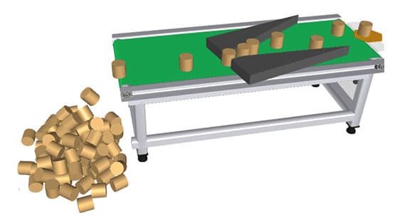
Physics
Components can have associated physical properties, such as free fall, braking and accelerating, being blocked or aligned by other bodies. See the cylinders falling, stacking, being aligned in the picture on the side.
Collisions
To make sure there are no collisions between some components it is good to set a minimum distance between them. The distance is then constantly monitored in the simulation run. If the minimum distance falls below the set value the simulation run is stopped and the affected component is marked in color.

The advantages of a CAD-simulation
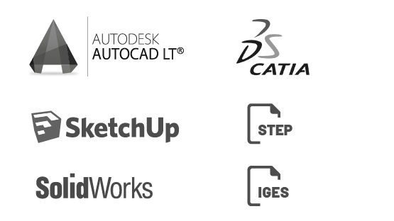
Visualization of reality
VC imports CAD directly from Step, Catia, SolidWorks, Unigrafics, AutoCAD, Parasolid, JTOpen, Iges, Igrip, 3D Studio, Sketchup, Rhino and many more CAD formats.
Geometries, splitting and rotary axes
Once imported, CAD geometries are simplified and split into smaller independent units. They may be then connected with each other with joints, which can be rotary axes or linear tracks. The joints have properties or can be even programmed to achieve its accurate movements behavior. For example they can be programmed with a kinematics routine that controls all joints in a robot so the robot can reach a particular position in space.

3D PDF
VC can save a 3D layout into a 3D PDF for even easier collaboration within the project team or as a reference for the customer. As every pdf file also the 3d pdf can be open with the popular Acrobat Reader.
Quality analysis of the simulation runs
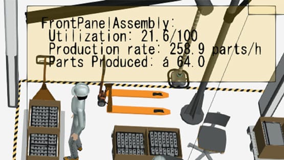
Exploit potential
With Visual Components it is possible to present the results in a variety of ways. The statistics on utilization, production rates and production volumes will be automatically collected by the components and visualized in the model.
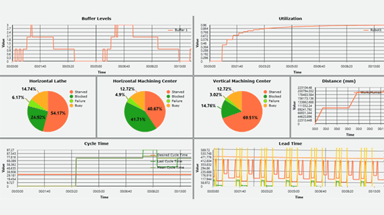
Dashboard
The values of statistics during the simulation run can be recorded and displayed in a dashboard. You can show this way the quantities in a buffer over the time or the momentarily position of each axis in a robot. With this it is straightforward to see how the axes have worked in the robot and which one is used the most extensively. Clearly structured dashboards help to understand complex relationships in the modeled systems.
Examples of models
What questions do you have about your simulation project?
Tell us what your project is about and we help you find a good solution.
PARTNERS:

SimulateFirst Poland
ul. Powstańców Śląskich 5
PL 53-332 Wrocław
polska@simulatefirst.com
+48 75 6406434
SimulateFirst Germany
Anton-Graff-Str. 24
D-01309 Dresden
dresden@simulatefirst.com
+49 (0) 351 30906020